This is not a tutorial created by Team Xecuter, neither can they be responsible for anything referring to this tutorial.
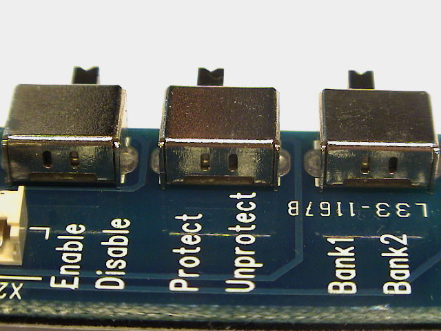
After some inspection I found that the switches on the external board is DPDT (Dual Pole Dual Throw) slide switches (two separate circuits), and that two of the three switches were only using one of the circuits. Other tutorials use an extra switch to control the LCLK connection to properly disable the chip, this tutorial is using the free circuit on the flash protection switch to control the connection.
I'll show the pin-head install because it the easiest, neatest, and it looks more professional than the wire install. But it's fully possible to adapt this tutorial for a wire install, just solder the LCLK and v5 wires to the black and red wires in the wire harness instead, respectively.
Before you start the modification you should flash the chip with a v1.6 comptiable bios, i.e Evox M8 1.6 (Note: KernelBasher can corrupt this bios, use the original bios to make sure the Xbox boots successfully).
You can either do this by hot swapping the chip on another already pin-head modded Xbox or you can use the X2 External Programmer and flash the new BIOS using X2 Bios Manager (Excellent tutorial by k3rn3l here). You should flash the bios to bank2 on the Xecuter chip otherwise programs might not launch properly.
I cannot reproduce this specific problem as I don't have the v1.6 Xbox anymore, but boot into the MS dashboard and set the clock if the Xbox lost track of time before you enable the chip.
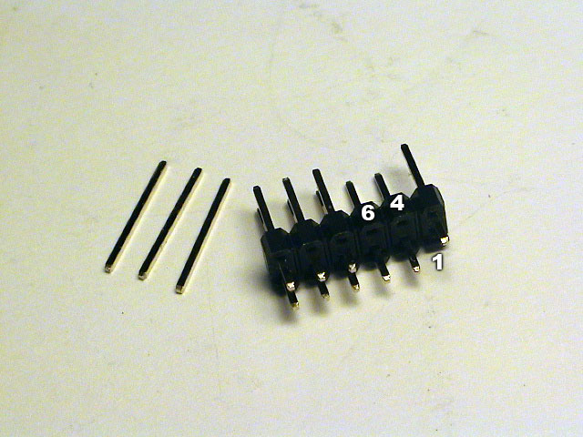
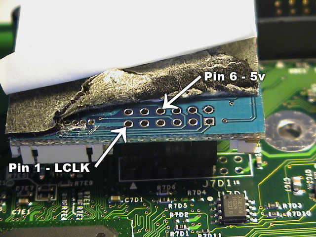
Remove the three pins from the pin-head shown in the picture. From the bottom-right, remove pin 1 (LCLK), pin 4 (empty) and pin 6 (5v)
Note: If you don't want to do the switch part, you should leave pin 1 (LCLK) untouched as it's needed for the chip to boot up properly.
|
|
|
| Three pins removed from pin-head. | Top LPC points. | Bottom LPC points. |
If you already have inserted and soldered the pin-head, you can either cut the pins near the plastic or if you want to completely remove the pin you can use some braid/wick to remove the solder and gently pull the pin out.
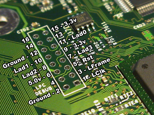
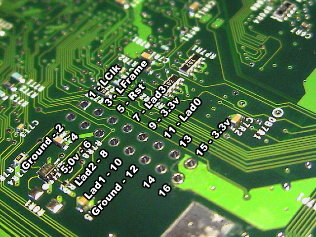
Use the official Xecuter 2.3b lite LPC rebuild instructions for further guidance.
 |
 |
 |
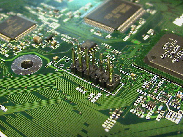
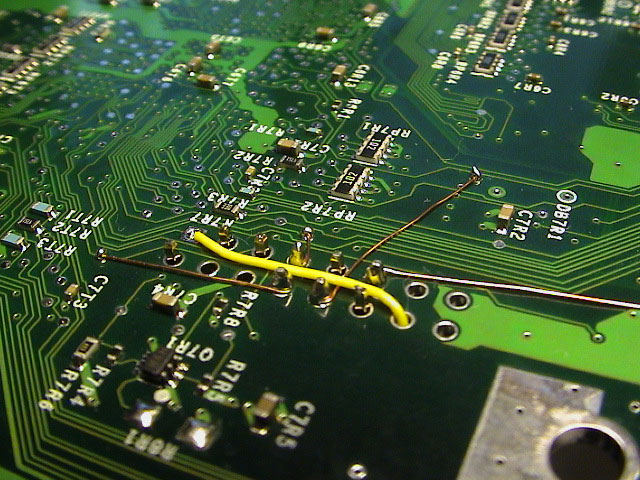
| Pin-head on top of the motherboard. | All LADs soldered to the respective LPC pins. | Overview |
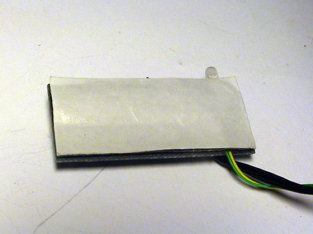
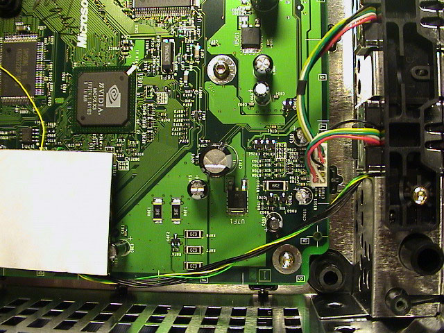
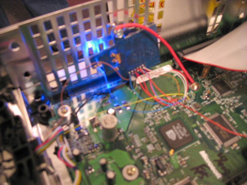
Position the Xecuter chip on the pin-head.
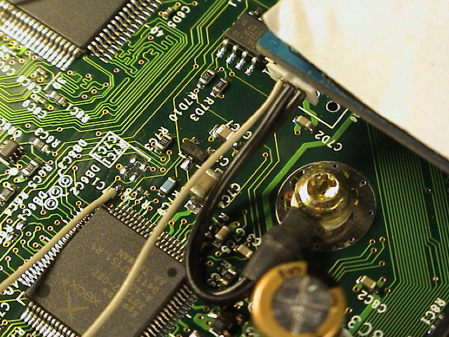
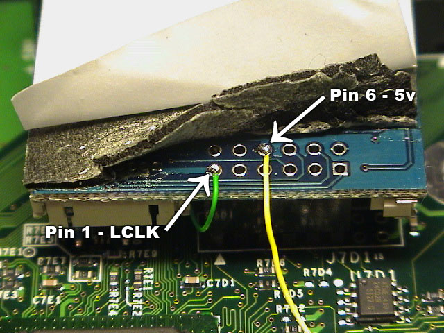
On top of the Xecuter chip remove the foam sticker from the opposite side where the pin-head is soldered, use some alcohol or similar to clean the points. Obviously the points are the same as on the motherboard, just that pin 1 (LCLK) and pin 6 (5v) isn't connected to the points on the motherboard. Attach a wire to the alt. 5v point and connect it to pin 6 (5v) on top of the Xecuter chip.
 |
 |
 |
| The alternate 5v point, for steady 5v when powered on, and 0v when powered off. | Pin 6 (5v) and pin 1 (LCLK) on top of the Xecuter chip. | Wire connected from alt. 5v to the 5v point on the chip. |
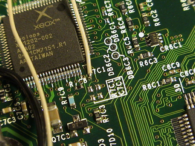
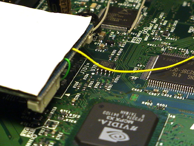
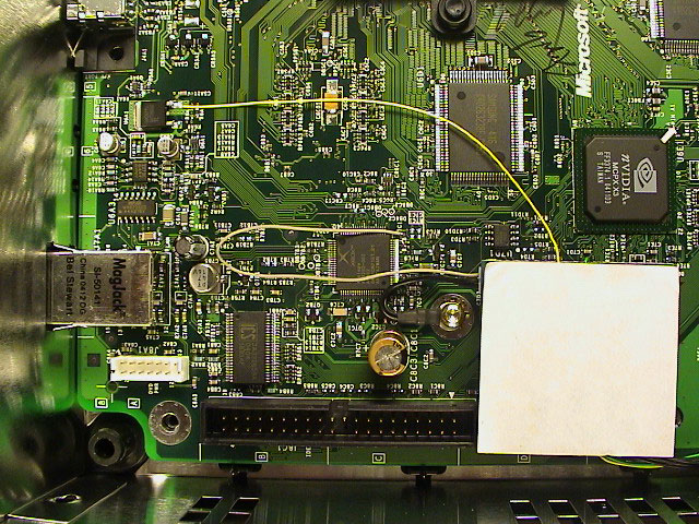
Cut the end of the grey D0 wire so just enough wire is exposed to cover the LFRAME point. Heat the LFRAME point for 2 seconds, add some solder to the point (not the iron), remove the solder then the iron, grab the wire, heat the solder and attach the wire to the LFRAME point.
 |
 |
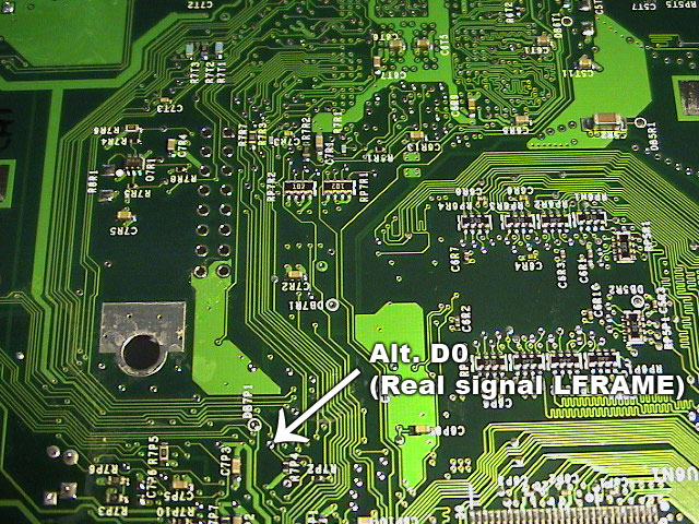 |
| LFRAME point next to the Xyclops chip. | D0 and ground wire attach to the chip. | Alternate D0 point on bottom of the motherboard. |
The trick I've found is that you can use a free circuit on an already existing switch on the external Xecuter board to break the LCLK connection. No need to buy and install an additional switch and stick it next to something that frankly already looks pretty ugly.
Note: If you don't want to use the free switch on the external board you can just use a regular SPST switch and solder the green and yellow wire to it, but I think adding an extra switch isn't worth the esthetical compared to the external board solution.
First things first, to avoid a mess later just follow the steps from top to bottom. First the LPC rebuild, then the alt. 5v, then the LCLK points on the Xecuter chip, and at last the points on the external Xecuter board after you've put the motherboard back into the case.
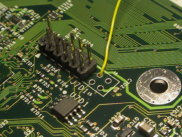
On the bottom LPC points, attach a wire from pin 1 (LCLK), the square one. Make sure that it's long enough to reach the front of the Xbox, measure using the external board wire harness and add a couple of inches to get a safety margin. Route the wire through one of the free holes. Now remove the chip from the pin-head and bend the wire towards the edge of the motherboard.
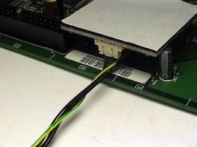
Reposition the chip to the pin-head. You should've already removed the foam sticker where the LPC points are located. Attach a wire to pin 1 (LCLK), it's the one in the middle of board closest to the edge. Make sure it's long enough.
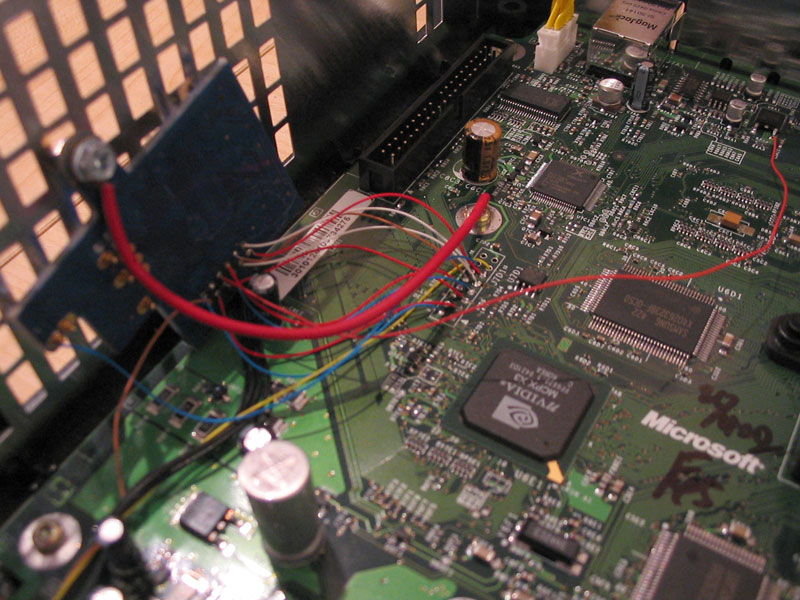
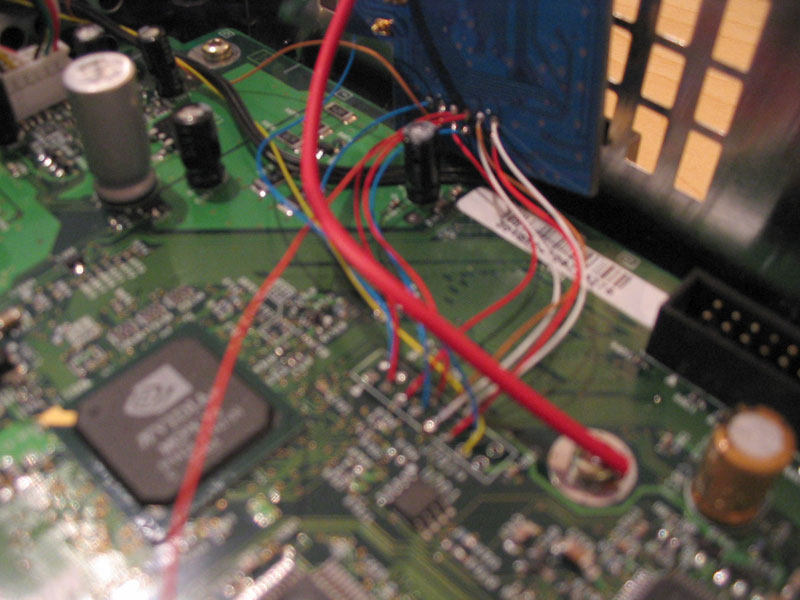
Attach the external wire harness to the chip and twist the two new wire around the harness.
Note: If you chose not to use the switch part above, you should just solder the pin you didn't remove (pin 1) as you normally would (like the LPC rebuild).
 |
 |
 |
| Attach a wire to the square (pin 1) point. | Route the wire through one of the free holes. | Bend it towards the edge of the motherboard. |
 |
 |
| Attach a wire to pin 1 (LCLK). Route the wire under the chip. Alt. 5v wire should already be soldered. | Twist the wires together. |
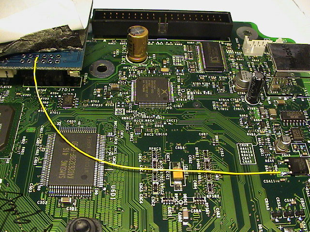
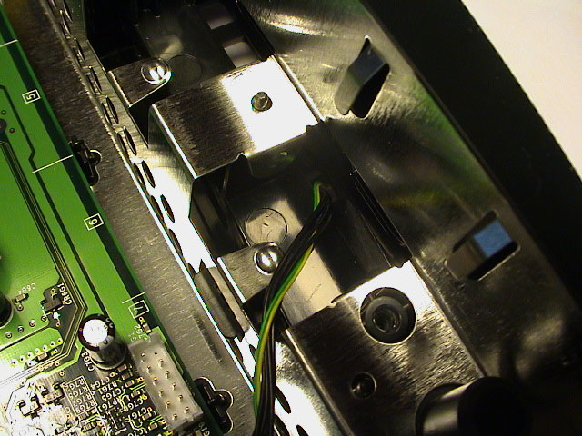
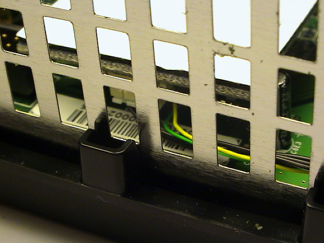
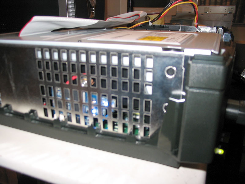
Remove the left controller board from the Xbox case, route the wires through controller port 1 and through the right hole seen from front.
 |
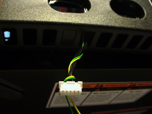 |
| Route through the right hole seem from front. | Wire harness with the two new LCLK wires. |
 |
 |
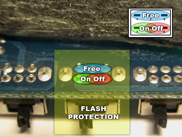
| Simple explanation. Bottom circuit is used for the flash protection and the top circuit is free/not used. | - |
Cut and attach the wire coming from pin 1 (yellow LCLK) on motherboard to the middle pin (pin 2) on the switch. Now you can select whether you want the flash protection enabled when the chips is disabled, or vice versa:
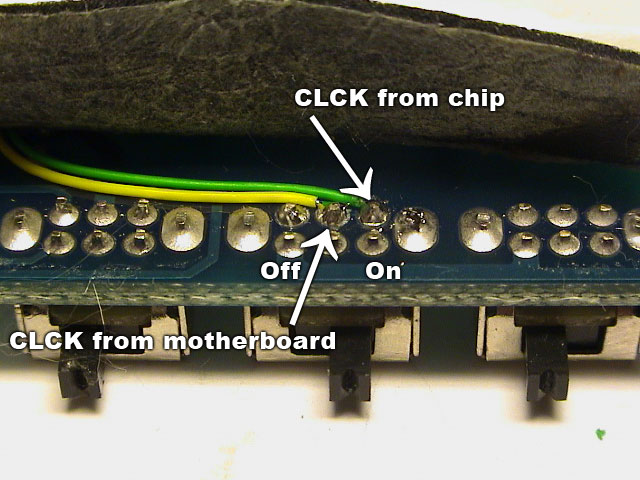 |
| Attach the yellow wire to the middle pin and the green wire the right pin. |
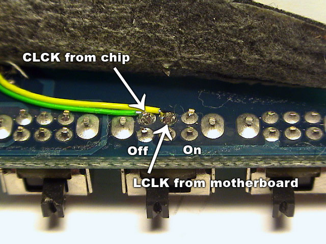 |
| Attach the yellow wire to the middle pin and the green wire the left pin. |
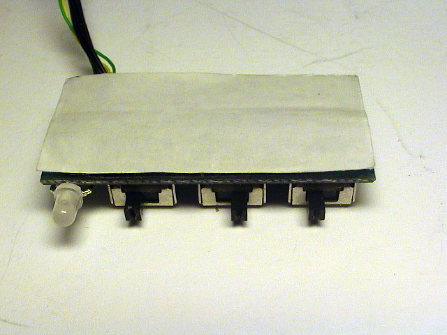
Wrap the wires under the foam sticker.
 |
 |
| - | - |
 |
 |
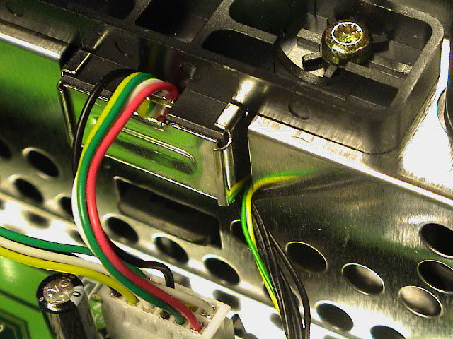 |
| 5v and LCLK (to switch) wires | External wire harness | Route to front |
 |
 |
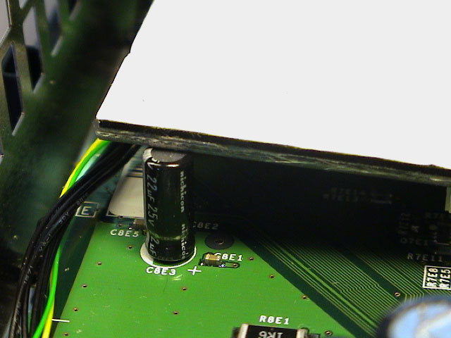 |
| Overview | Overview | This capacitor will tilt the chip. |
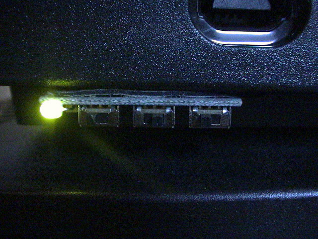
Unprotected when enabled / Protected when disabled (Recommended method)
Enabled + Unprotected = Boot from chip (Green LED)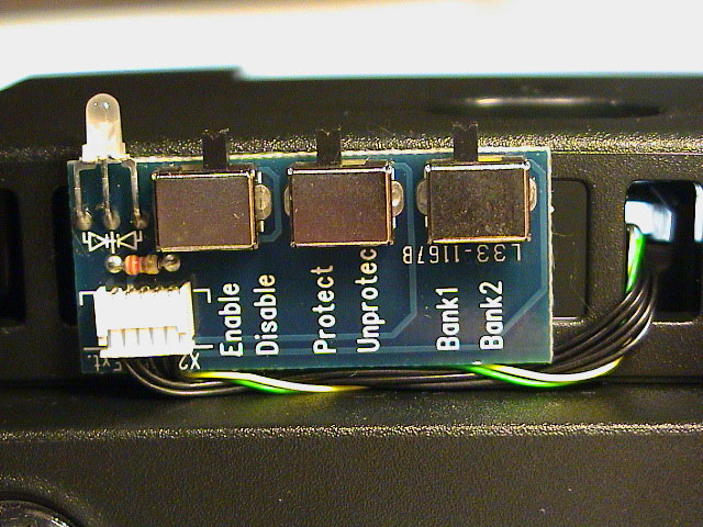 |
 |
|
Enabled
|
Disabled
|
 |
 |
It's pretty important that you flash the chip with a compatible v1.6 BIOS before you start installing. The LPC points on the bottom side of the Xecuter 2.3b lite plus chip is exactly the same as the one you find on top of the motherboard. Knowing that you can easily figure out where to connect the extended wires. Use the pictures below as a guideline.
Thanks to James for the pictures and additional information.
 |
 |
 |
| Alternate 5v to the right, ground is double connected to the original point and to the case and D0 is connected to the alternate (bottom) LFRAME. | On the bottom of the Xecuter chip are the LPC points exactly the same as on top the motherboard. | The yellow wire is going from the bottom LCLK (pin 1) point on the motherboard and to the external switch. |
 |
 |
|
| The chip is held to the side using the hole where ground usually is connected to the motherboard. | The orange wire is connected from the external switch to the LCLK (pin 1) point on the Xecuter chip. |
I don't have much information about this chip yet, but I'm certain that you will need an extra switch since the external board is using dip switches and the only slide swich available does not have any free circuits that the external board on the Lite have. The only possible install would be to do the above install and either connect an external switch for the LCLK connection or just connect it straight to the motherboard. If you choose to do the latter one you won't be able to disable the chip (the Xbox will frag when the chip is in disable mode).
Xecuter 2.3b lite wire install
Xecuter 2.3b lite pin-head install
2004