

I'll show you the pinhead method because it's the simpliest, easier to remove the chip, and you get a good connection to the LPC points.
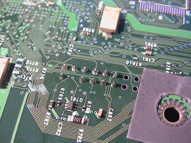
Before you attach solder to the LPC points on the bottom side the motherboard, you should first clean the points with some isopropanol alcohol and tin the solder ircon, this makes it much easier to handle the solder and get a good result. Now, hold the ircon on the LPC point for 1 second to warm it, the feed some solder the point itself not the iron. The solder should flow around the point, if you get a solder topping when you remove the iron you need to add some flux and reflow the solder. The points should shine, if they are grey and rough you got a cold solder - reflow it with some flux and hold it still for 3-4 seconds. Do this for the rest of the points.
|
|
|
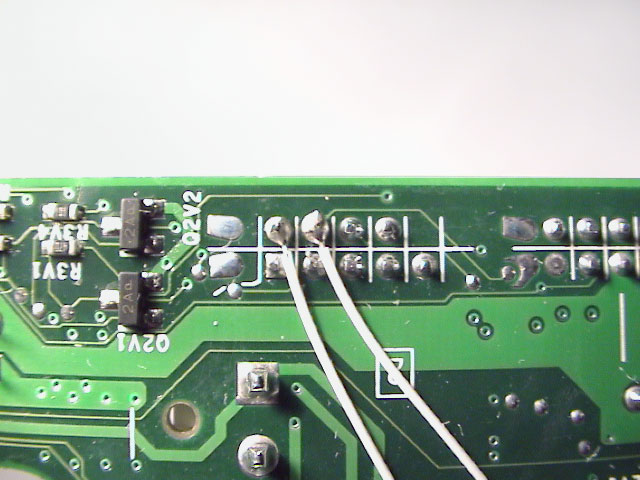
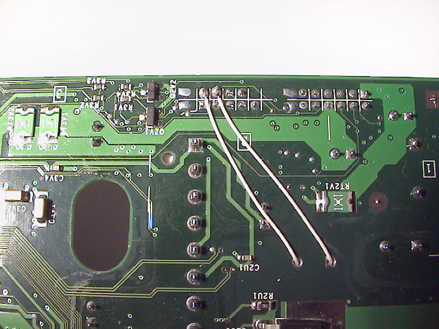
| Bottom side of the unsoldered LPC points | Soldered LPC points | Top side of the soldered LPC points |
Attaching wires to the D0 and A15 points was rather easy (easier than I thought acually), cause the wires I use was small enough to fit through the points and easier to solder when they can't move.
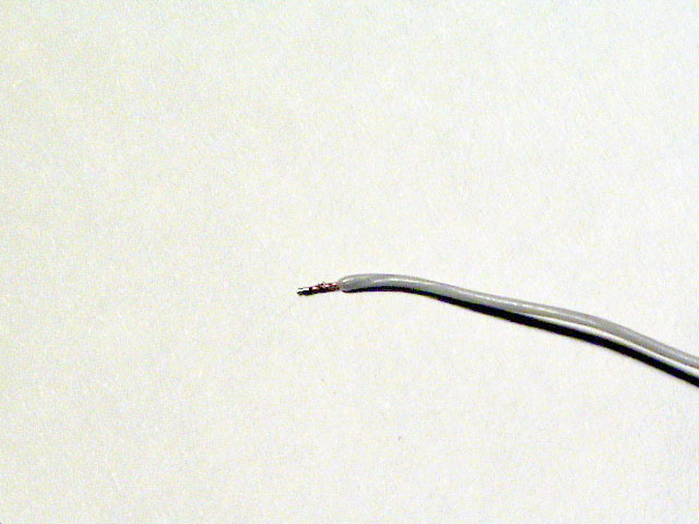
First I cut off around 5 mm of the insulation.
 |
| Plain, already cut, 30 AWG wire |
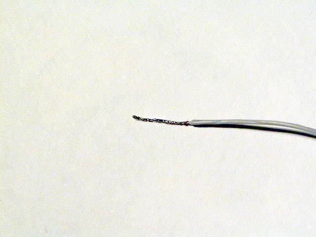
Then I added some solder to the wires by dragging them over the solder iron till sufficent solder attached. Now cut the excess wire, only 1-2 mm of the stripped wire should be visible.
 |
 |
| Wire with solder attached | Soldered and cut wire |
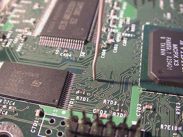
This way I can just touch the wires with the solder iron and the solder will melt around the point. Do this with the D0 and possible A15 points if you want the ability to flash the TSOP onboard bios (corrently not fully functional).
 |
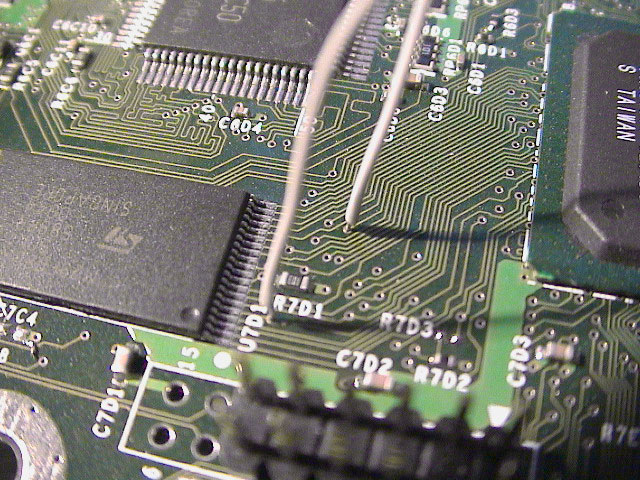 |
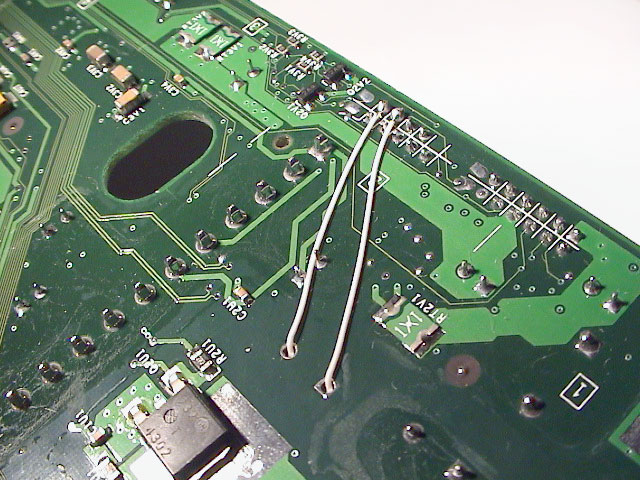
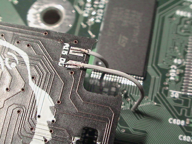
| Wire attached to the D0 point | Wires attached to both D0 and A15 points |
Update: I found it easier to make some slack for easier removal of the chip.
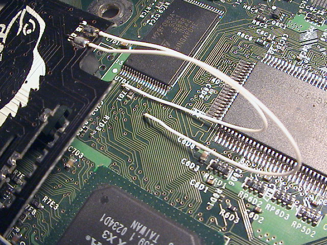 |
 |
| Slack for easy removal. | Another view. |
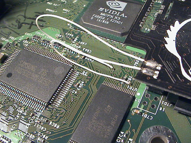
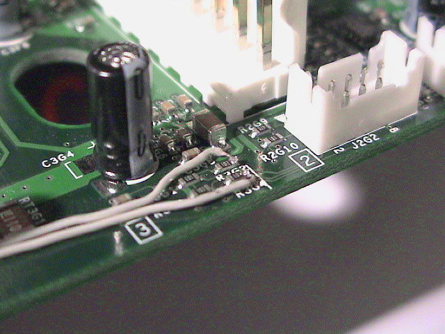
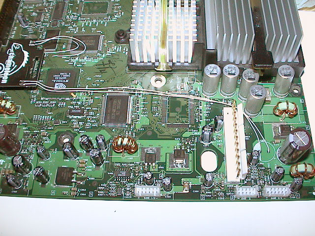
You only need to attach wires to the Eject (E) and Power (P) points if you want to run your Chameleon in Mode 4 and be able to disable the chip. You disable the chip by holding the eject button (think eject-mod-chip-button, easier to remeber). If you start the Xbox with the power button the xbox will start up in bank1 (256k) and if you start the xbox with both eject and power buttons pressed the xbox will start up in bank2 (256k). More on this later.
 |
 |
 |
| Wires attached to the Power (top) and Eject (bottom) points | Another view | P and E wires reaching the Chameleon |
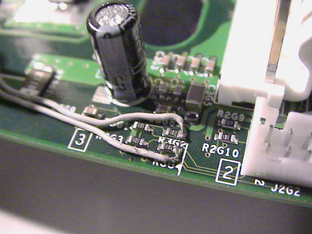
 |
 |
 |
 |
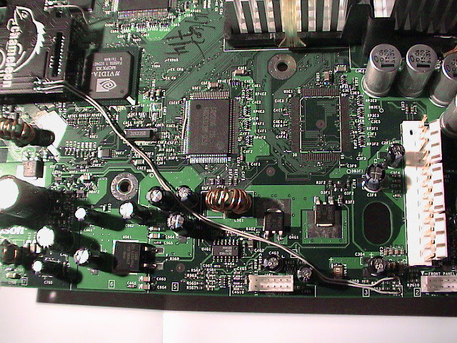
| The P point is left and the E right. The first method leads the wires through the big hole. | Another view. | Yet another view. | This is how I wired the top. |
Now your ready to attach the wires to the Chameleon. Bend and position the wires, cut off, and strip the wires.
 |
| D0 and A15 wires ready to be attched to the points on the Chameleon |
Now use either the solder iron or some kind of knife to remove the insulation on the wires. This can be a bit tricky because the points or the wire can easily break if you acedently drag and push the wire. I used the solder iron to melt the plastic. It's pretty easy to attach the wires, just add some solder to the points and the wires, heat the solder on the chip, attach the wires, remove the iron and hold still for 3-4 seconds. The solder will not flow outside of the square points if you used flux to wet them, but this is not strictly needed since there is already some flux in the solder itself and on the points.
 |
 |
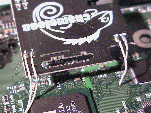 |
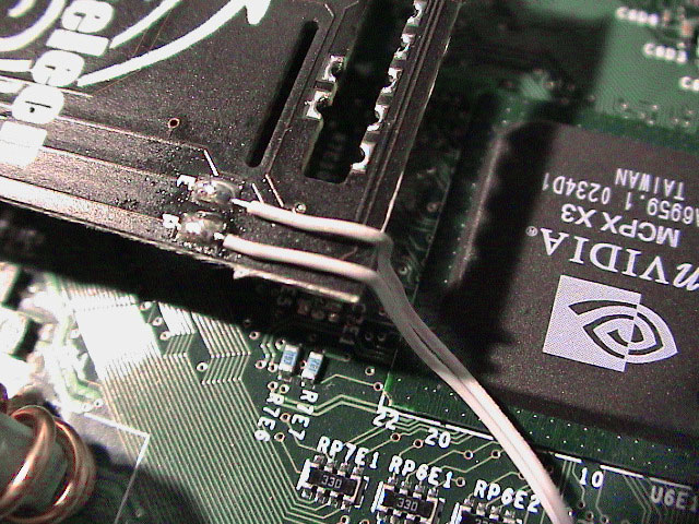
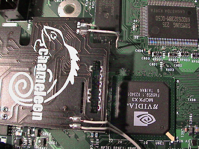
| P and E wires attached to the corresponding points on the Chameleon (perfect solder points eh? :) | Overview of the Chameleon with all four points soldered | Another view |
Now you've installed the Chameleon mod-chip! Reassemble the Xbox and power it up and you'll see the Cromwell Linux Bios splashscreen. Follow the bios guide to replace it with another more feature rich bios.